
|
| Impact Injury Analysis of Hard and Soft Structures of Living Organisms by the Dynamic Explicit FEM |
|
|
The head of the human body comprises cranial bones (hard tissues) and the brain (a soft tissue). The primary objective is the development of a simulation method to predict the damage in cranial bones and the brain when the head receives an impact load.
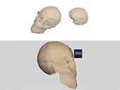
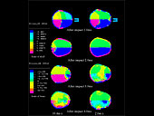
Accordingly, an ESI head model, which is a finite element model of human body material (Fig. 1), was used for analysis. The deformation behavior and stress propagation when various rigid bodies collided with the head at an arbitrary angle and with an arbitrary speed were analyzed by using the dynamic explicit finite element method, i.e., PAM-CRASH (ESI) (--> Reference List (1)–(3)). The results when a tubular-type rigid body collided with the anterior or upper posterior region of the head at 10.4 m/s or 2.6 m/s are shown in Fig. 2.
The figure shows that the stress was concentrated at a region slightly posterior to the center of the brain.
In addition, it also indicates that negative stresses are applied on the side opposite to the region where collision occurred and that the stress wave propagates inhomogeneously. This is because the brain is considered to comprise multiple components, and hence, the stress is not propagated uniformly. Moreover, it was also found that the absolute values of the propagation speed in the cranial bones are different from those in the brain, and the magnitudes of the stress wave that is transmitted into the brain are smaller than the magnitudes of those transmitted into the cranial bones. Apparently, this is because the cerebrospinal fluid that is present between the cranial bones and brain alleviates the stress. However, the results of investigations of actual brain disorders reveal that diffuse cerebral impairment, in which the whole brain is deformed, accounts for a large part of the brain damage in consequence of being collided with rigid bodies.
We attempted using the simulation to direct the research; however, a comparative verification using the simulation result and the actual phenomena is difficult, and therefore, this research was temporarily suspended.
|
|
|
|
Fig. 1 ESI Head Model
|
|
|
|
| Fig. 2 Propagation of Stress Waves |
|
 |
|
| Investigation of the Construction Method of Hexahedral Finite Elements using the Full-color Cross-sectional Images of Living Organisms |
|
|
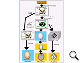
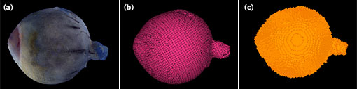
| We conducted a simulation of the retinal detachment operation using the finite element method (FEM). Here, the method for the construction of a hexahedral FEM mesh of an eyeball model that is designed for the simulation of a retinal detachment operation was investigated. First, a method to convert the segmented data (--> Nobunori Kakusho’s page) of the continuous cross-sectional images of a human eyeball, which were obtained using a three-dimensional (3D) internal structure microscope (--> Hideo Yokota’s page), into the conformation model was explored. Image data are converted to polygons, which are surface data with isosurfaces, by using AVS5.3; the information of the polygons were listed in the coordinate form. Hence, the image data can be converted to conformational data (Fig. 3). |
|
|
|
Fig. 3 (Please click on the figure to enlarge it.)
|
|
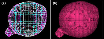
Subsequently, an FEM mesh (Fig. 5) was constructed by projecting a hexahedron-shaped template box onto the surface data by the mapped mesh method using the ICEM CFD/HEXA (ANSYS). In addition, a voxel mesh was constructed based on the continuous cross-sectional images obtained by using VOXCELCON (Quint), and these meshes were compared to determine the most appropriate mesh that could be used as information for the simulation.
|
|
Fig. 4 Mapped Mesh Method
(a) Template Box, (b) Mapped Mesh |
At this time, it was believed that the number of meshes was approximately equal. The meshes and 3D image are shown in Fig. 5. The mapped mesh showed a conformation nearly identical to that of the 3D image. [Note: Please check the change.] However, the concavity and convexity of the voxels in the continuous cross-sections are apparent in the voxel model. Further, the surface conformation of each tissue is not depicted. Consequently, it was confirmed that the hexahedron mesh constructed using the mapped mesh method is more effective since it demonstrated continuous cross-sectional images with a fewer number of meshes than expected.
|
|
Fig. 5 Image and Mesh
(a) Volume Rendering, (b) Mapped Mesh, (c) Voxel Mesh |
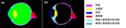
Meshes that are continuous among the tissues of an eyeball were constructed by using the method described here. As shown in Fig. 6, boundary surfaces among the tissues indicate that they are continuous and share contact points. Moreover, thin membrane layers could be suitably reproduced by the meshes. In the future, the accuracy of this method must be improved.
|
|
Fig. 6 Image and Mesh
(a) Image, (b) Mesh Model |
|
|
|
| Development of the Compression Testing Equipment for a Hyperelastic Body |
|
|
|
|
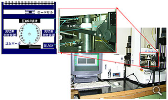
| Fig. 7 (Please click on the figure to enlarge it.) |
| We conducted a simulation of the retinal detachment operation by using the FEM. Currently, although the program has been completed, verification of the extent to which the program can simulate the actual phenomenon has not been evaluated. Thus, an experimental system was constructed to verify the reproducibility of the program (Fig. 7). The values obtained by the analysis are the changes in conformation, stresses applied, and inner pressures generated when a hyperelastic body is compressed incrementally by a uniform value. In order to obtain the values, a soft tennis ball filled with water is compressed using a precision universal testing machine (Shimadzu), and the pressure during compression is measured using a strain gauge pressure sensor (SENSOTEC). Additionally, the change in conformation can be measured using a z-axis stage that is position-controlled by an electric motor so that a laser sensor (Omron) could move vertically. The values measured by using the equipments are analog outputs and imported into a computer equipped with an AD converter board to generate data in the CSV format. By computing the measured data after the test, it becomes possible to semi-automatically measure the amount of compression, inner pressure, and external dimensions. This facilitates the analysis of experimental results. Currently, the measurement system and its control system have been completed, and tests have been initiated. |
|
|