
|
| [1] Numerical Analysis of Blood Flow in the Cerebral Artery and Cerebral Aneurysm |
|
|
|
|
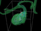
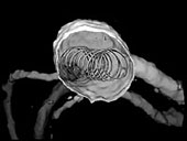
Fig .1 Analysis of blood flow in the cerebral aneurysm
A virtual coil generated by computer graphics (CG) is superimposed on a three-dimensional structure obtained by three-dimensional computed tomography angiography (3D CTA). |
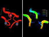
Fig. 2 Analysis of blood flow in the cerebral artery and the Willis ring that are obtained by smoothing of the 3D CTA-derived three-dimensional structures |
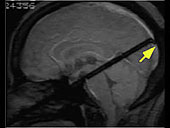
Fig. 3 Blood flow visualization by using tagged MRI.
The signal-inhibiting region that is indicated by a yellow arrow (a band in black color) shows blood flow with time. |
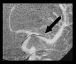
Since the development of cerebrovascular disorders such as cerebral aneurysm was considered to be affected by blood flow patterns, an environment to analyze cerebrovascular disorders by using computational fluid dynamics (CFD) was created. Medical image data such as angiography with computational tomography (CT) and magnetic resonance imaging (MRI) are basically obtained as sequential cross-sectional images. From these sequential cross-sectional images, three-dimensional blood vessel structures were extracted and analyzed by CFD (Fig. 1). Since the resolution of the medical image was inadequate for blood flow analysis, the image was converted into a smoothing model (Fig. 2) by H. Liu and H. Iwase. Although blood flow analysis was mainly performed for cerebral aneurysm, the analysis for the pre- and postoperative high-grade carotid artery stenosis was occasionally performed. Blood flow analysis is expected to provide important information that can be used to select the treatment method for cerebrovascular disorders such as cerebral aneurysm.
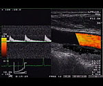
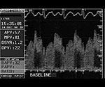
In order to use CFD, boundary conditions must be determined. In this study, tagged MRI (phase contrast) (Fig. 3) and ultrasonic Doppler method (Fig. 4) were applied to obtain the boundary conditions. To observe the influence of gravity on the blood flow, angiography was performed in the standing posture.
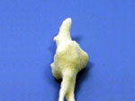
Along with computational analysis, an experiment with a model was considered important for blood flow analysis. Therefore, a hollow blood vessel model (Fig. 5) was constructed from the abovementioned three-dimensional medical images by using a rapid prototyping (RP) modeling machine. In comparison with a previously reported method in which resin was injected into postmortem blood vessels, the method described in this study can construct a model of a blood vessel of a living patient for various purposes such as fluid simulation. |
|
|
|
Fig. 4-1 Ultrasonic Doppler method
The Doppler signal of the internal flow in the palpable artery was received by a probe placed on the body surface.
|
Fig. 4-2 Ultrasonic Doppler method
Blood flow information can also be obtained for the intracranial vessel through a Doppler probe attached to the tip of a wire. |
|
|
Fig. 5 A hollow cerebral blood vessel model
A model (left) constructed with an RP modeling machine was wrapped in silicon resin and then melted to produce a replica of the cerebral blood vessel (right). |
|
|
|
| [2] Development of a Catheter Simulator |
|
|
Recently, an intravascular operation (Fig. 6) for the treatment of cerebrovascular disorders such as cerebral aneurysm has been developed. This operation enabled the occlusion of an abnormal blood vessel or restoration of its patency by introducing a tube (catheter) from the thigh up to the target lesion. Although intracranial diseases can be treated with only catheters without requiring an open surgery, training in the use of catheters is difficult and time consuming.
|
|
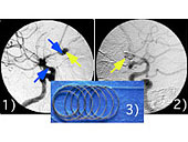
Fig. 6 An intravascular operation (coil embolization) for the treatment of cerebral aneurysm
By introducing a catheter in the cerebral aneurysm as shown by the CG (left), the aneurysm is occluded and its rupture is prevented.
1), A coil (shown in 3)) is introduced in the aneurysm (yellow arrow). 2), The blood flow in the aneurysm (yellow arrow) is stagnated and occlusion is achieved. The blue arrows in 1) indicate X-ray impermeable markers on the microcatheter used to introduce the coil. |
|
The development of a catheter treatment simulator (Fig. 7) was initiated to train operators or treat abnormal blood vessels whose treatment with a catheter is difficult. Currently, we are simulating the operation step that involves the use of a guide wire, which is necessarily used with a catheter. In the simulation, a three-dimensional blood vessel structure obtained from a patient’ image is used as the blood vessel structure, and the elasticity of the guide wire is also considered. Simulation of the movement of the X-ray fluoroscope that is used for the treatment and the images generated by X-ray fluoroscopy has been almost completed. This simulation is expected to contribute to the future development of a comprehensive simulator, including a catheter. Moreover, we aim to develop teletherapy and robot surgery by constructing a master-slave system in combination with an actuator.
|
|
|
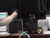
Fig. 7 A teletherapy system using PHANToM
When PHANToM in the left is operated, PHANToM 6DF on the right reproduces the operator’s movement. |
|
|
|
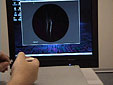
Fig. 8 A guide wire simulator
As shown in the left photograph, a virtual guide wire was placed in a three-dimensional blood vessel structure obtained from medical image data. As shown in the right photograph, the guide wire operation was imported by an encoder, and the operation was simulated. |
|
The guide wire operation using PHANToM, a haptic device, has already been successful (Fig. 8). |
|
| [3] Observation of the Fine Coil Structure for Arterial Embolization by Micro CT |
|
|
The typical embolization material used for endovascular treatment is a detachable platinum coil. Although the coil is mainly used for thrombogenesis by indwelling it in the cerebral aneurysm lumen, its fine structure could not be observed by clinical fluoroscopy. When an enucleated sample of the cerebral aneurysm was observed with Riken’s micro CT, a damaged coil (Fig. 9) in the aneurysm was confirmed.
It is believed that this phenomenon was not reported because coil embolization was uneventful and the damaged coil could not be detected by clinical fluoroscopy.
During coil embolization, the maximum amount of the coil indwelled in the aneurysm is equivalent to 20%–30% of the aneurysm’s inner volume. Therefore, there is a possibility that the blood flow in the aneurysm is not completely occluded. Since the part of the coil at the neck of an aneurysm is always pushed by blood flow, the stability of the coil cannot be maintained for a long duration. The data obtained by measuring the three-dimensional structure of the coil by micro CT can be used to detect the secular deformation of the coil and to perform computational simulation. |
|
|
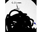
Fig. 9 Fluoroscopic image of a coil obtained by micro CT
A damaged coil was confirmed at the site indicated by the blue arrow. The coil diameter (primary diameter) was approximately 0.35 mm, and the coil was a platinum wire (filament) approximately 0.0044 mm in diameter. Since the coil was damaged, a piece of filament can be directly observed at the site indicated by the blue arrow. |
|
|
|
|
|
|
|
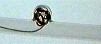
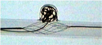
Fig. 10 A neck remodeling device
As shown in the left photograph, indwelling the coil in the wide neck aneurysm was difficult, and the coil protruded from the aneurysm. As shown in the right photograph, the coil could be stably indwelled when a basket was installed under the coil. |
In the case of cerebral aneurysm embolization, treatment of a wide neck aneurysm with a somewhat compressed shape is difficult. This is because the spiral-shaped memory coil protrudes from the wide neck aneurysm. Therefore, a basket (Fig. 10) was developed in order to support the coil to avoid its protrusion from the aneurysm.
This basket is commercially available and mainly used for the collection of foreign bodies, fragments, and thrombus. |
|
| [5] Preparation of Digital Teaching Materials |
|
|
|
|
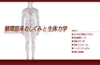
| Fig. 11 Mechanism of the circulatory system and biomechanics |
In cooperation with NHK Software, “Mechanism of the Circulatory System and Biomechanics,” a digital teaching material of the Japan Science and Technology Agency, was prepared (Along with K. Fukasaku, some members of this project also participate in the preparation of teaching materials. Please refer to Fig. 12). More information is available at http://www.rikanet.jst.go.jp/G012TitleList.html. These teaching materials can be used in all high schools in Japan.
|
|
| Fig. 12 Production and supervision (detailed information is available by clicking here) |
|
|